

книги / Переработка нефти и газа
..pdfFig. 6. Basic flow sheet of isobutene alkylation with butylenes:
1 – reactor (contactor); 2 – settlement tank for acid; 3 – driers; 4 – isobutene separation tower; 5 – n-butane separation tower; 6 – alkylate separation tower; 7 – compressor; 5 – separator; 9 – propane tower;
streams: I – primary material; II – circulating isobutane; III – acid; IV – reaction products used to cool down the reactor; V – n-butane; VI – light alkylate; VII – heavy alkylate; VIII – propane; IX – isobutane return
Process conditions:
•reactor temperature – 5–10 °С (could range from 0 to 12 °С); lower temperatures sharply reduce acid viscosity, while higher temperatures cause intense oxidization of olefins;
•agitator’s shaft speed – 400–500 rpm;
•duration of primary material contact with sulfuric acid – from 20 to 30 minutes;
•pressure – 0.3–1.0 MPa required to keep primary material liquid phase condition;
•primary material feed velocity – 0.1–0.6 m–1, including that required for the whole acid amount;
•acid-to-hydrocarbons ratio in reaction zone is (1–1.1):1;
•isobutane-to-olefins ratio in reaction zone is (6 10):1.
91
Alkylation process products:
•light alkylate, cut С5 – 190 °С with yield accounting for 70–80 % of the total charging of mix, motor octane number = 93–95. It is used as one of the major high-octane components of gasoline (aviation and motor gasoline);
•heavy alkylate, a cut upwards of 190 °С with yield accounting for 3–5 % represents a concentrate of isoalkanes. It is used to obtain solvents or jet fuels, could be used as a component of diesel fuels;
•waste butane cut with yield accounting for 10–15 % (depending on butane content in primary material). It contains: 70 % of n-butane, 3 % of isobutane and 27 % of sum of С5. It is used by GFU to extract components from saturated gases or included into gasoline to enhance its true vapor pressure;
•propane accounting for 2–8 % (depending on quality of primary material).
Alkylation process development prospects are primarily connected with using up to 50 % of BBC in the process as a primary material without sacrifice of alkylate quality. Apart from this, the BBC resources could be enhanced by the dehydration of n-butane and obtaining of butanes.
Another promising direction is the combination of alkylation with obtaining MTBE. Alkylate will be most successfully produced with the use of n-butenes and less successfully with the use of isobutylene that is a target component in making MTBE.
Should isobutylene be extracted from final boiling gas by MTBE synthesis, isobutane-to-olefins (butenes) ratio in the remaining gas becomes favorable for alkylation.
The same applies to pyrolysis gas following butadiene extraction from it, but it is poor in isobutane, therefore in the course of alkylation, it should be added.
Fig. 7 shows basic diagram of unsaturated gases rational use. Once through two GFUs, BBC (III and IV) are directed to MTBE production, following which the both cuts free from isobutylene are directed to alkylation, and all components are directed to commercial gasoline production.
92
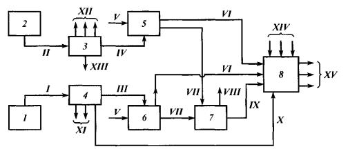
Fig. 7. Basic Diagram of Unsaturated Gases Rational Use:
1 – catalytic cracking; 2 – pyrolysis; 3, 4 – GFU; 5, 6 – MTBE production; 7 – alkylation; 5 – commercial gasolines production;
streams: I, II – cracking and pyrolysis processes gases; III, IV – BBF; V – methanol; VI – MTBE; VII-BBC without isobutylene; VIII – heavy alkylate; IX – light alkylate; X, XIII – cut С5+; XI – dry gas and PPC; XII – dry gas, PPC and butadiene; XIV – компоненты cracking, reforming etc. gasoline components, XV – commercial gasolines of various brands
Composition of gas flows as per the above Diagram is shown in Table 1. Roman numerals in the Table correspond to numbers of streams in fig. 7. As it is shown, following isobutylene extraction, concentration of butanes sharply increases, and composition of primary materials becomes more favorable for alkylation.
Composition of pyrolysis and cracking gases as per Diagram shown in fig. 7
Hydrocarbons |
|
Pyrolysis gas |
|
Cracking gas |
||
II |
|
VII |
I |
|
VII |
|
|
|
|
||||
Isobutane |
2 |
|
5 |
40 |
|
47 |
n-Butane |
3 |
|
10 |
10 |
|
12 |
Isobutylene |
25 |
|
– |
15 |
|
– |
Butene-1 |
19 |
|
55 |
10 |
|
12 |
Butene-2 |
10 |
|
30 |
25 |
|
29 |
Butadiene |
41 |
|
– |
– |
|
– |
93
Lecture 2
SYNTHESES ON THE BASIS OF CARBON OXIDE AND HYDROGEN
Carbon oxide and hydrogen (synthesis-gas) could be obtained as a result of gasification of coals, shales and heavy oil residues.
Table 1 shows a summary of potential synthesis processes on the basis of carbon oxide and hydrogen, their properties and end products.
|
|
|
|
|
Table 1 |
|
Syntheses on the basis of carbon oxide and hydrogen |
||||||
|
|
|
|
|
|
|
Process |
Catalysts |
Promoting |
Temperature, |
Pressure, |
Product |
|
agent |
°С |
MPа |
||||
|
|
|
||||
Synthesis of methane |
Ni |
ТhО2 or |
250–500 |
0.1 |
Methane |
|
|
|
МgО |
|
|
|
|
Synthesis of higher |
Со, Ni |
ТhО2, МgО, |
150–200 |
0.1–1 |
A mixture of paraffins |
|
hydrocarbons |
|
ZrO2 |
|
|
and olefins С1-С100 |
|
Synthesis of higher |
Fе |
Сu, NaОН |
200–230 |
0.1–3 |
Predominantly paraffins |
|
hydrocarbons and |
|
(КОН), |
|
|
and olefins mixed with |
|
oxygen-containing |
|
Аl2О3, SiO2 |
|
|
oxygen-containing |
|
compounds |
|
|
|
|
compounds |
|
Synthesis of paraffins |
Со |
ТiO2, ZrО2, |
190–200 |
1 |
Predominantly solid |
|
|
|
ТhО2, |
|
|
paraffins with melting |
|
|
|
|
|
|
temperature of 70–98 °С |
|
|
Ru |
МgО |
180–200 |
10–100 |
High-molecular |
|
|
|
|
|
|
paraffins |
|
Isosynthesis |
ТhО2, |
К2СО3 |
400–450 |
10 |
Paraffins and olefins |
|
|
ZrO2, |
|
|
|
predominantly with |
|
|
Аl2O3 |
|
|
|
isomeric structure |
|
|
ТhО2 |
– |
350–500 |
10–100 |
Isoparaffins and |
|
|
|
|
|
|
aromatic hydrocarbons |
|
Synthesis of methanol |
ZnО, |
– |
200–400 |
5–30 |
Methanol |
|
|
Сг2O3, |
|
|
|
|
|
|
СuО |
|
|
|
|
|
Synthesis of higher |
Fе, Fе-Сг, |
А12О3, |
180–220 |
1–3 |
Methanol and higher |
|
alcohol |
Zn-Сг |
NаОН |
380–490 |
15–25 |
alcohols |
|
1. Fischer Tropsch synthesis
Synthesis of hydrocarbons on the basis of СО and Н2 is a heterogeneous catalytic process that releases large amount of heat. Major products are paraffin hydrocarbons (mainly of normal structure) and olefins. However, the recent researches have enabled to obtain catalysts facilitating the generation of aromatic and cycloparaffin hydrocarbons.
94
Fischer Tropsch reaction results in producing hydrocarbons according to the following equations:
A-type reactions: |
|
|
(2n+1)H2 + nCO = CnH2n+2 + nH2O, |
(–165 kJ/mole) |
|
2nH2 |
+ nCO = CnH2n + nH2O. |
(–165 kJ/mole) |
A-type reactions: |
|
|
2nH2 |
+ 2nCO = CnH2n+2 + nСO2, |
(–207.9 kJ/mole) |
nH2 + 2nCO = CnH2n + nСO2.
Peculiarities of Fischer Tropsch synthesis (F-T) are high reaction heat (about 35 % of synthesis-gas combustion heat) and the need for very accurate maintenance of the reaction temperature, which are hardly compatible. For example, about 3,000 kJ of heat would be released per 1 cubic meter of synthesis gas. Such an amount of heat is sufficient to bring 1 cubic meter of gas to 1,500 °С.
In 1945 total capacity of F-T units was 1 million tons of hydrocarbons a year. In 1945–1962, all such units were dismantled, but at the same time in 1956 South Africa commissioned Sasol-1 unit.
Subsequently, two other units have been built: Sasol-2 (1981) and Sasol-3 (1984), 2 million tons a year each. Worth mentioning is that Sasol-2 is a fluidized bed unit, due to which the present total capacity of Sasol units is 5 million tons a year.
Atmospheric pressure synthesis takes place in plate reactors, while high-pressure synthesis – in pipe reactors. Recently, fluidized bed reactors have been applied. Table 2 below shows their essential difference in terms of specific capacity, gasoline and diesel fuel yield and other properties.
Classical synthesis products are gaseous hydrocarbonds С1-С4, liquid paraffin and olefin hydrocarbons and solid paraffin. Normally, F-T catalyzate is divided into three wide cuts:
95
Table 2 Comparative characteristics of F-T synthesis processes in reactors of various types
Properties |
Fixed-bed reactor |
Fluidized-bed |
|
reactor |
|||
|
|
||
Reaction volume capacity |
8–58 |
115 |
|
С3 and higher, kg/m3 |
|
|
|
Yield: |
|
|
|
С1 + С2, g/m3 |
10–35 |
35 |
|
С3 and higher, g/m3 |
125–170 |
150 |
|
gasoline, % of liquids |
18–70 |
73 |
|
diesel fuel, % of liquids |
10–35 |
7 |
|
heavy oil + paraffin, % of liquids |
1–56 |
3 |
|
oxygen–containing compounds, % of liquids |
1–12 |
17 |
|
Gasoline octane number |
37–54 |
76 |
|
Diesel fuel cetane number |
50–90 |
50 |
Gasoline has low octane number as it contains predominantly normal paraffin hydrocarbons and therefore it is directed to catalytic reforming, which brings its octane number to 95–96. It could also be subjected to pyrolysis to obtain ethylene.
Diesel fuels represent mixtures of paraffin hydrocarbons with insignificant content of olefins. Cut 180–320 °С is used as a high-cetane additive (CN = 70–90) to diesel fuels, as well as for producing high-quality oils (by chlorination and subsequent condensation with aromatic hydrocarbons).
Paraffins and ceresins are obtained due to vacuum distillation of high-boiling synthesis products. This results in soft and slab wax (cut 320–460 °С) and solid paraffin-ceresin (drop point 110–115 °С).
Generally, depending on process properties, interrelationship of end products could widely vary, due to which such products could be used to obtain either motor gasoline, or motor gasoline and diesel fuel or other products.
Hydrocarbons were synthesized with the use of various catalysts, but for the time being, standing out among the variety of the catalysts are metals of Group VIII i.e. iron, cobalt, nickel and ruthenium that have proved particularly active in hydrocarbons synthesis.
Base metal of catalysts includes various additives (promoting agents) that increase reaction rate and make it more selective.
Particularly efficient modifiers for iron catalysts are salts of alkali metals (e.g. К2СО3).
Synthesis gas entering the unit shall without fail be made free of sulfur compounds (maximum 0.2 g of sulfur per 100 m3 of gas is allowed).
96

Synthesis reaction is extremely exothermal (about 16,000 kJ of heat release on the average per 1 kg of resultant liquid products), while optimum synthesis temperatures for nickel and cobalt catalysts are 170–250 °С, for iron catalysts 200–235 °С, and for ruthenium ones – 160–225 °С. Therefore, reaction heat withdrawal is the primary problem of synthesis.
Rational pressure for various catalysts: nickel catalyst pressure shall be close to atmospheric level, cobalt and iron catalysts pressure could be increased by 2 MPa, ruthenium catalyst would only properly operate at 10 MPa.
All catalysts are very sensitive to sulfur compounds, halogens, heavy metals and resinous substances. Therefore, gas shall undergo deep pre-treatment.
Reactor represent the major vessel of the F-T process. The first commercial units were equipped with plate reactors that had many disadvantages. Subsequently introduced and widely applied for the time being are shall and tube reactors with concentric pipes (the space between them is filled with catalyst).
The latest achievement in the sphere of Fischer Tropsch synthesis is fluidized-bed catalyst process developed by Kellog Company. Diagram of unit Sasol-3 (South Africa) looks as follows (fig. 1).
Fig. 1. Diagram of Fischer Tropsch fluidized-bed process (Kellog Company):
1 – lift-reactor; 2 – catalyst separator; 3–5 – separation towers; 6, 9 – compressors; 7 – furnace; 8 – gas treatment tower;
streams: I – circulating hydrocarbon gas; II – reaction products; III – sludge; IV – heavy oil; V – water + water-soluble products; VI – synthesis gas; VII – gasoline; VIII – residual gas; IX – water; Х – steam
Compressor 6 supplies synthesis gas through pipe furnace 7 with the temperature of 160 °С and pressure of 2.2. MPa to mix it with separator 2 catalyst having the temperature of 350 °С, following which synthesis gas enters vertical lift-reactor (bottom upwards). Lift-reactor contains two tiers of water pipe coolers. Leaving the
97
lift-reactor, the mixture enters a separator, from the bottom of which the catalyst is going to be mixed again with synthesis gas, while reaction products from the top are directed to separation module. The separation module’s towers produce heavy oil, gasoline, residual gas and sludge. The reactor has diameter of 2 m, height of 30 m, the catalyst circulation rate is 6,000 tons per hour. Amount of the initial synthesis gas is 90–100 thousand cubic meters per hour.
2. Methanol Synthesis
World demand for methanol not including production of high-octane gasoline from methanol using Mobile process is shown in Table 3.
|
Trends of the world demand for methanol |
Table 3 |
||||
|
|
|||||
|
|
|
|
|
|
|
Application |
|
Demand for methanol, thousand tons |
|
|||
1978 |
|
1985 |
1990 |
|
1995 |
|
|
|
|
||||
Chemical raw materials |
10,105 |
|
13,330 |
17,000 |
|
21,000 |
MTBE production |
85 |
|
1,200 |
3,000 |
|
10,000 |
Gasoline additive |
245 |
|
695 |
2,900 |
|
5,000 |
Total |
10,345 |
|
15,225 |
22,900 |
|
36,000 |
Raw material is synthesis gas with CO-to-Н2 ratio ranging from 1:5 to 1:10. Catalysts are made as zinc-chromium (BASF) or zinc-copper (Lurgi). Zinc-chromium catalysts operate at the temperature of 360–380 °С, pressure of 25–30 MPa, velocity up to 60,000 hr–1; zinc-copper ones at the temperature of 220–280 °С and pressure of 4–6 MPa.
At present, there are about 25 plants in the world making ammonia and methanol of synthesis gas obtained from coal. Their capacity is up to 1,000 tons of methanol a day. Their high capital expenditures are offset by low raw material costs.
One of the widespread processes is methanol production process using Lurgi technique at the pressure of 5 MPa (fig. 2). The process includes obtaining of synthesis gas from heavy oil residues or coal, its thorough cleaning and then obtaining of methanol. Methanol synthesis takes place at 250–260 °С. Worth mentioning is that per 1 kg of methanol 1.4 kg of high-pressure gas is obtained.
98
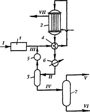
Fig. 2. Methanol synthesis using Lurgi technique:
1 – synthesis gas cleaning unit; 2 –methanol synthesis reactor; 3 – separator; 4 – heat exchanger; 5 – compressor; 6 – cooler; 7 – methanol rectification tower;
streams: I – crude synthesis gas; II – reaction products; III – gas to recirculation; IV – liquid catalyzate; V – methanol; VI – bottom products; VII – high-pressure steam
Methanol could be used to obtain motor fuels in the following options:
•methanol as a substitute for gasoline;
•methanol as an additive to gasolines;
•methanol as a raw material for making high-octane gasoline components (MTBE, MTAE etc.);
•methanol as a raw material for making high-octane gasoline.
A substitute for gasoline. In terms of its certain significant properties (octane number, consumption of combustion air), methanol outperforms the best grades of gasoline, although it has a number of disadvantages: low mass combustion heat, high boiling heat, high hydrophilic property, toxicity and corrosive power towards certain metals. Therefore, methanol has never been applied in the pure state as an alcohol fuel.
Addition of methanol low amounts (2–7 %) requires no engine re-design, as in this case, methanol would never display its corrosive power. A serious problem consists in the delamination (phase separation), if water enters the gasoline-methanol mixture. Depending on gasoline composition and amount of methanol, delamination takes place at various temperatures. However, methanol added to gasoline leads to decrease
99

of harmful emissions into atmosphere and makes octane number higher. Despite of these obvious advantages, application of gasoline-methanol mixtures has so far been restricted.
3. Synthesis of Gasoline from Methanol
Introduction of high-silica zeolites enabled to develop the technique of transforming methanol into hydrocarbons. Worth mentioning is that this process is high-selective and yield high-octane gasoline. Thermal efficiency of the process approximates 90 %. Its raw material i.e. methanol could be used wet and not pre-treated.
The most widely known is Mobil Oil process (fig. 3). The process flow sheet includes: lift-reactor, separator, regenerator linked with overflow pipes. Reaction products from the separator through the cooler enter a tower used to separate gasoline and water. Lift-reactor will be cooled down throughout its height in a number of areas in order to withdraw large amount of excessive heat. Methanol is delivered to the liftreactor bottom. The catalyst is special-purpose made of zeolite. 1 ton of methanol yields 440 kg of hydrocarbons and 560 kg of water.
Fig. 3. Reactor Module of Unit used to synthesize Gasoline from Methanol:
1 – reactor; 2 – reactor separation area; 3 – regenerator; 4 – phase separator; 5 – cooling jackets;
streams: I – methanol vapor; II – gasoline; III – water; IV – gas; V – air; VI – smoke fumes; VII – reaction products; VIII – regenerated catalyst
100