

Учебное пособие 2006
.pdfRussian Journal of Building Construction and Architecture
|
|
|
к |
|
|
|
к |
|
|
|
к |
¯ |
|
|
|
, |
(19) |
||
|
|
|
|
|
|
|
|
|
|
|
|
2 |
|
|
|||||
|
|
|
|
|
|
|
|
||||||||||||
|
|
|
|
|
к |
|
|
|
|
к |
|
¯ |
|
2 |
. |
|
(20) |
||
|
|
к |
|
|
к |
|
|
||||||||||||
Let |
|
|
|
|
|
|
|
|
|
|
|
||||||||
|
|
|
|
¯ |
|
к |
|
|
|
|
, |
|
|
|
(21) |
||||
|
|
|
|
|
|
|
|
|
|
|
|
||||||||
the expression(10) takes the following form: |
|
|
|
|
|
|
|
|
|
|
|
||||||||
|
|
|
к |
|
|
|
at к к . |
|
|
|
(22) |
||||||||
Inserting (22) into equation (20), we get:
|
к |
к |
кк |
|
к |
¯ |
|
к |
к |
¯ |
к к |
|
к |
|
|
к |
к . (23) |
|
|
|
|
|
|
|
|
|
|
|
|
at |
|
2 |
|
|
2 at |
|
|
|
|
|
|
|
|
|
||||||||||||
In order to express the stresses of the structural elements of the hybrid rack in the longitudinal direction, let us introduce:
|
|
|
|
|
|
|
|
к |
|
|
|
|
к |
|
|
|
|
|
|
, |
|
|
|
|
|
|
|
|
|
|
(24) |
||
where K |
|
|
|
|
|
|
|
|
|
|
|
|
|
|
|
|
|
|
|
|
|
|
|
|
|
|
|
|
|
||||
|
|
|
|
|
|
on (23) and are equal to: |
|
|
|
|
|
|
|
|
|||||||||||||||||||
к and Kb are obtained based |
|
|
|
к |
¯ |
|
|
|
|
|
к, |
|
|
|
|
|
|
|
(25) |
||||||||||||||
|
|
|
к |
|
|
|
к |
|
к |
|
|
|
|
|
к |
|
|
|
|
|
|
|
|
|
|
|
|||||||
|
|
|
|
|
|
|
|
|
|
|
|
|
|
|
at |
|
|
2 at |
|
|
|
|
|
|
|
|
|||||||
|
|
|
|
|
|
|
|
|
|
|
|
|
|
|
|
|
|
|
|
|
|
||||||||||||
Then the original stresses of the |
shell1 |
|
кк |
|
|
|
к ¯ |
|
|
|
|
|
|
|
к |
. |
|
|
|
|
|
|
|
(26) |
|||||||||
and core of the2hybrid |
rack in the longitudinal direction |
||||||||||||||||||||||||||||||||
are equal to: |
|
|
|
|
|
|
к |
|
|
|
|
|
|
|
|
, |
|
|
|
|
|
|
|
|
|
|
|
|
|
||||
|
|
|
|
|
|
|
|
|
|
|
|
|
|
|
|
|
|
|
|
|
|
|
|
|
|
(27) |
|||||||
|
|
|
|
|
|
|
|
|
|
|
к |
|
|
|
|
|
|
|
|
|
|
|
|
|
|||||||||
|
|
|
|
|
|
|
|
|
|
|
|
|
к |
|
|
|
|
. |
|
|
|
|
|
|
|
|
|
|
|
|
|
(28) |
|
Then it is possible to calculate the compressive |
loadк |
N acting at the stress |
к |
, |
|
using one of |
|||||||||||||||||||||||||||
the below formulas: |
|
|
|
|
|
|
|
|
|
|
|
|
|
|
|
|
|
|
|
|
|
|
|
|
|
|
|
|
|
|
|
||
|
2 |
|
2 |
|
|
|
|
|
к |
|
|
|
|
|
|
|
, |
|
|
|
|
|
|
|
(29) |
||||||||
|
|
|
|
|
|
|
|
|
|
|
, |
|
|
|
(30) |
||||||||||||||||||
|
|
|
|
|
|
|
|
|
|
|
к |
|
|
|
|
||||||||||||||||||
|
|
|
2 |
|
|
|
2 |
|
|
|
|
|
|
|
к |
|
|
|
|
к |
|
|
|
|
(31) |
||||||||
|
|
|
|
|
|
|
|
|
|
|
|
|
|
|
|
|
|
|
|||||||||||||||
Apart from dependences |
(27)2and |
(28), the2 |
longitudinalк stresses |
of the structural. |
elements of |
||||||||||||||||||||||||||||
the hybrid rack can be calculated from the expressions obtained from equations (30) and (31):
к к, (32)
80

Issue № 2 (50), 2021 |
ISSN 2542-0526 |
|
|
. |
(33) |
|
к
Therefore the dependences of the operation in the elastic stage of the hybrid rack made of fiberglass shell filled with monolithic concrete are obtained.
4. Estimation of the load-bearing capacity of a hybrid rack under the influence of compression. The above expressions are compiled according to the parameters of materials characteristic of the elastic stage of their operation, thus they are only valid at the initial stage of loading the rack. In the case of exposure to the rack of a considerable amount of compression load, the concrete goes beyond the elastic stage of operation, as a result of which the stresses calculated by the derived formulas (22, 32, 33) are unacceptably overestimated. By the time the stresses in the concrete exceed 0.5 ÷ 0.7 Rb (prismatic compressive strength), the elasticity modulus of concrete starts changing based on a nonlinear law as the compressive force rises. A well-studied and commonly used method is known for calculating the stresses of concrete during nonlinear operation. A simplified three-line diagram based on the type of Prandtl diagrams (in accordance with SP 63.13330.2018 –– "Concrete and Reinforced Concrete Structures") is adopted as a working diagram of the state of concrete, which identifies the relationship between stresses and relative deformations. The stresses of the concrete rod σb depending on the corresponding relative deformations of the shortening of concrete εb are given by the formula:
|
|
1 |
|
|
|
|
|
|
|
|
, |
(34) |
where |
|
|
0,6 |
|
|
|
||||||
|
|
|
|
|
, |
|
(35) |
|||||
|
|
|
|
, |
|
|
(36) |
|||||
εb0 are the largest longitudinal values of relative deformations of concrete depending on the relative humidity of the surrounding air.
The longitudinal stresses of concrete under volumetric compression increase fairly considerably and can greatly exceed the prismatic strength Rb. The criteria for the strength of concrete are used to identify he values of stresses where the strength of concrete is maintained under the conditions of triaxial compression. For the case of triaxial compression of concrete, A. A. Gvozdev's strength criterion for bulk compressed concrete is commonly used [4]:
, , (37) where β is the parameter of the material.
81

Russian Journal of Building Construction and Architecture
The results of N. I. Karpenko's experimental-theoretical studies [7] and the results of the later work by other researchers showed that the parameter β is not a constant value, but rather is described by the dependence [8]:
, (38)
where b = 0.096, a = 0.5b, f = 1 are empirical coefficients of concrete.
Note that in the above design, the longitudinal stresses of the shell are always a lot lower than the corresponding ones in concrete due to a considerable difference in their cross-sectional areas. Thus despite the fact that the concrete core operates outside the elastic stage based on the nonlinear law, the shell at the same time operates predominantly elastic (except for the stage of destruction in the transverse direction if it takes place).
Following the calculation of the parameters characterizing the stress-strain of the hybrid rack, the load-bearing capacity of the hybrid rack under the action of compression is evaluated. It is considered that the integrity of the structure of the rack under the action of compression is preserved if the strength conditions for each of its elements are satisfied:
|
|
|
|
к,р |
, |
|
|
|
(39) |
|
|
|
|
|
, |
|
(40) |
||
|
|
|
к |
к,с |
|
, |
(41) |
||
|
|
|
|
|
|
, |
|
|
|
where |
are ultimate tensile |
transverse stresses from the evenly distributed pressure on the |
|||||||
|
|
|
|
|
|
||||
wall ofσtheк,р |
fiberglass shell |
к,с |
are ultimate stresses while compressing fiberglass in the longi- |
||||||
tudinal direction. |
|
|
|
|
|
|
|
||
Checking the durability of a hybrid rack on the bending moment is performed as for a regular reinforced concrete rack of a round section. It is possible to consider the strength characteristics of the fiberglass shell as an additional reinforcement of the structure.
Conclusions. A model of the stress-strain of the hybrid rack intended for supports of bridge constructions is designed and scientifically substantiated. It considers the deformation interaction of a comprehensively compressed concrete core with an anisotropic fiberglass shell. Expressions identifying stresses and relative deformations in the longitudinal and transverse directions during compression of a hybrid stand are formulated. It is found that the concrete core operates outside the elastic stage based on the nonlinear law whereas the shell operates mainly elastically, except the stage of destruction in the transverse direction if it takes place.
82
Issue № 2 (50), 2021 |
ISSN 2542-0526 |
The above results contribute to the development of a calculation method for hybrid reinforced concrete racks with external fiberglass shells. This technique will enable one to estimate the compressive load-bearing capacity considering the nonlinear operation of the concrete core, its interaction with the shell, various parameters of fiberglass in the longitudinal and transverse directions. The proposed design parameters characterize the limit states of each element of the hybrid rack, which in compliance with the requirements of modern regulations ensures the safety, reliability and durability of the designed structure.
References
1.Aleksandrov A. V., Potapov V. D., Derzhavin B. P. Soprotivlenie materialov [Resistance of materials]. Moscow, Vysshaya shkola Publ., 2008. 559 p.
2.Berg O. Ya., Shcherbakov E. N., Pisanko G. N. Vysokoprochnyi beton [High-strength concrete]. Moscow, Stroiizdat Publ., 1971. 208 p.
3.Berg O. Ya. Fizicheskie osnovy teorii prochnosti betona i zhelezobetona [Physical foundations of the theory of strength of concrete and reinforced concrete]. Moscow, Gosstroiizdat Publ., 1961. 96 p.
4.Gvozdev A. A. Raschet nesushchei sposobnosti konstruktsii po metodu predel'nogo ravnovesiya [Calculation of the load-bearing capacity of structures using the limit equilibrium method]. Moscow, Izd-vo i tip. Stroiizdata, 1949. 280 p.
5.Drobyshevskii B. A. Problemy malogo mostostroeniya [Problems of small bridge construction]. Transportnoe stroitel'stvo, 2005, no. 11, pp. 22––24.
6.Ivanov A. N. Sovershenstvovanie konstruktsii i metodiki rascheta proletnykh stroenii mostov s nesushchimi elementami iz kompozitsionnykh materialov. Avtoref. diss. kand. tekhn. nauk [Improvement of the design and calculation methods of bridge spans with load-bearing elements made of composite materials. Cand. eng. sci. diss. abstr.]. Novosibirsk, 2015. 22 p.
7.Karpenko N. I. Obshchie modeli mekhaniki zhelezobetona [General models of reinforced concrete mechanics]. Moscow, Stroiizdat Publ., 1996. 412 p.
8.Karpenko N. I., Karpenko S. N. [Composite criterion of concrete strength under volumetric stress state]. Beton i zhelezobeton – vzglyad v budushchee: tr. III Vserossiiskoi i II Mezhd. konf. po betonu i zhelezobetonu [Proc. “Concrete and reinforced concrete-a look into the future”], 2014, vol. IV, pp. 156––165.
9.V. V. Vasil'ev e.a. Kompozitsionnye materialy: Spravochnik [Composite materials: Reference book]. Moscow, Mashinostroenie Publ., 1990. 510 p.
10.Kikin A. I., Sanzharovskii R. S., Trull' V. A. Konstruktsii iz stal'nykh trub, zapolnennykh betonom [Structures made of steel pipes filled with concrete]. Moscow, Stroiizdat Publ., 1974. 145 p.
11.Luksha L. K. Prochnost' trubobetona [Strength of pipe concrete]. Minsk, Vysheish. Shkola Publ., 1977. 96 p.
12.Malashkin Yu. N. Deformirovanie i razrushenie betona v usloviyakh slozhnykh napryazhennykh sostoyanii. Avtoref. diss. kand. tekhn. nauk [Deformation and destruction of concrete under complex stress conditions. Cand. eng. sci. diss. abstr.]. Moscow, 1984. 38 p.
83

Russian Journal of Building Construction and Architecture
13.Ovchinnikova T. S., Marinin A. N., Ovchinnikov I. G. Korroziya i antikorrozionnaya zashchita zhelezobetonnykh mostovykh konstruktsii [Corrosion and corrosion protection of reinforced concrete bridge structures]. Internet-zhurnal «Naukovedenie», 2014, no. 5 (24), pp. 1–25. Available at: https://naukovedenie.ru/ PDF/06KO514.pdf.
14.Kerber M. L. e.a. Polimernye kompozitsionnye materialy: struktura, svoistva, tekhnologiya [Polymer composite materials: structure, properties, technology]. Saint-Petersburg, Professiya Publ., 2008. 557 p.
15.Solov'ev B. V., Malyasova E. N. Osobennosti proektirovaniya i ekspluatatsii zhelezobetonnykh avtodorozhnykh mostov s uchetom vozrosshikh nagruzok ot transporta [Features of the design and operation of reinforced concrete road bridges, taking into account the increased loads from transport]. Vestnik YuzhnoUral'skogo gos. un-ta. Ser.: Stroitel'stvo i arkhitektura, 2009, no. 35 (168), pp. 14––15.
16.Yashin A. V. [Criteria for strength and deformation of concrete under simple loading for various types of stress state]. Trudy Akad. stroitel'stva i arkhitektury SSSR. Nauch.-issled. in-t betona i zhelezobetona "NIIZhB". Vyp.39: Raschet i konstruirovanie zhelezobetonnykh konstruktsii [Proc. of the Acad. construction and architecture of the USSR. Scientific research. in-t concrete and reinforced concrete "NIIZHB". Issue 39: Calculation and design of reinforced concrete structures]. Moscow, 1977, pp. 48––57.
17.ElGawady M. A., Dawood H. M. Analysis of segmental piers consisted of concrete filled FRP tubes. Engineering Structures, 2012, no. 38, pp. 142––152.
18.Hamrick C. FRP bridge decks: A green double–leaf. Roads & Bridges. Roads & Bridges, 2012, no. 3, pp. 46––51.
19.Hoffard T. A., Malvar L. J. Fiber-reinforced polymer composites in bridges: a state-of-the-art report. Naval Facilities Engineering Service Center. Port Hueneme: NAVFAC, 2005. 38 p. Available at: https://archive.org/details/DTIC_ADA526493/mode/2up
20.Kendall D. Developments in FRP bridge design. Reinforced Plastics, 2010, no. 54 (3), pp. 38––42.
21.Potyrala P. B. Use of fibre-reinforced polymers in bridge construction. State of the art in hybrid and allcomposite structures. Barcelona, 2011. 93 p. Available at: https://upcommons.upc.edu/handle/2099.1/12353.
22.Watson R. J. Field Condition Surveys of FRP Applications on Bridges. Proceedings of the Second International Conference on Durability of Fibre Reinforced Polymer (FRP) Composites for Construction, Montreal, May 29––31. Sherbrooke, Université de Sherbrooke, 2002, pp. 597––606.
84

Issue № 2 (50), 2021 |
ISSN 2542-0526 |
ARCHITECTURE OF BUILDINGS AND STRUCTURES.
CREATIVE CONCEPTIONS OF ARCHITECTURAL ACTIVITY
DOI 10.36622/VSTU.2021.50.2.007
UDC 711.582
S. A. Gilev1
METHOD OF DESIGNING RESIDENTIAL COMPLEXES IN VORONEZH WITH THE USE OF BLOCK-SECTIONS OF COMPLEX CONFIGURATION
Voronezh State Technical University1
Russian Federation
1 Аssociate Professor of architectural design and urban planning, Professor, honored architect Russian Federation, Assoc. Prof. of the Dept. of Architectural Design and Urban Planning, Prof.,
Chairman of the Board of SRO Association of Chernozem Designers, RAASN adviser, e-mail: l001@list.ru.
Statement of the problem. Improving the architectural and artistic appearance of the new development of the city, its individualization has long been an urgent problem. In the 1960s and 70s, many houses were built in Voronezh according to standard projects, which made the development of new areas of the city monotonous and of the same type. New districts in different cities of our country have lost their identity, have become similar to each other.
In Voronezh, the monotony and monotony of new built and under construction areas such as Shilovo, Otradnoye and other microdistricts have created a problem that again needs to be solved. The development is very monotonous and impersonal, because it is conducted according to standard (re-used) projects with a very limited list of standard sections.
Results. The methodology of the approach to design proposed by the authors of the projects of residential complexes allowed us to implement a number of objects of mass development quite interesting, not similar to each other. The article analyzes several residential complexes of mass development built in Voronezh, the architectural originality of which was achieved through the development and use of block sections of complex configuration.
Conclusions. The use of sections of complex configuration can help urban planners working on projects of new residential complexes to find original space-planning solutions that ensure the uniqueness of the development of Voronezh. The architectural and artistic quality of the new districts, provided that they are unique and diverse, will be worthy of the historical center of the city of Voronezh.
Keywords: problems of mass development, quality of construction, block sections of complex configuration, organization of development.
Introduction. Since the 1960s the issues of uniformity of mass construction of this country’s cities have attracted a great deal of attention of architectural critics [1, 2, 4, 11, 20]. A. V. Ikonnikov and A. E. Gutnov, V. L. Glazychev and other famous Russian architects [3, 4, 5, 6, 7, 8, 9, 10, 12, 13]. mentioned this in their work.
© Gilev S. A., 2021
85

Russian Journal of Building Construction and Architecture
The problem of monotony in building new residential areas of Voronezh is still urgent. Considering that the new master plan of Voronezh provides for a significant rise in the reconstruction in the central areas, the problem of uniformity and scale of construction is only exacerbated [19, 26, 27]. M.G. Barkhin [1, 2] and M.V. Posokhin [18] speculated on the reconstruction of the city. The image of the urban environment concerned Le Corbusier [15, 22] and Oscar Niemeyer who are the leaders of modern architecture. The architect’s creative method was analyzed by the Voronezh scientist Yu. I. Karmazin [14]. These works should help city planners to address difficult problems of reconstruction of the central areas of our city. The aim of the article is to analyze several residential complexes built at the turn of the century and to identify the impact of the block-section design method on the architectural quality of these objects.
Nowadays when residential areas are being constructed on an unprecedented scale, it is almost impossible to achieve an individual image of each individual building [16]. The design technique set forth by the authors shows that achieving a variety of architectural and artistic approach to the design of residential complexes is possible by using block sections of complex configuration providing different methods of building layout [3]. Recently sections of complex configuration have almost not been used in mass construction. This considerably limits the compositional possibilities of construction making it more uniform [17]. Note that in the new series of large-panel residential buildings used by the Voronezh Housing Construction Plant (hereinafter DSK), there are no even corner block sections. In this regard, the construction of new districts Shilovo and Otradny (developer –– DSK Voronezh) is formed by large-panel houses consisting of regular block sections placed meridionally, and occasional monolithic buildings. The absence of angular, rotary and other sections of complex configuration in the DSK nomenclature considerably limited the designers’ compositional capacities.
1. Formation of a block-section design method in Voronezh. The historic development of the city has witnessed multiple examples of the construction of residential buildings of complex configuration. Voronezh is known to have been severely destroyed during the war with only 1/10 of the housing stock surviving the attacks. The city was included on the list of 15 historic cities of the USSR, which were rebuilt following the government’s a special decree. The project of the general plan of revival of the city was performed under the direction of the known Soviet architect, academician L. V. Rudnev [1]. The city was rapidly rebuilt, and soon its center gained its current features of the «Stalin’s Empire» [9, 18, 21, 23]. During the reconstruction of Voronezh following the war, repetitive layouts of ordinary sections were
86

Issue № 2 (50), 2021 |
ISSN 2542-0526 |
frequently used, but corner, rotary and other sections of complex configuration were invariably designed individually depending on the urban situation. In the 1960s, in the wake of the struggle against architectural excesses, the use of houses of complex configuration was abandoned. Representative houses were built in four or six block sections with no architectural detail. The block-section design method started its revival as late as in the 1970s [8, 10]. In the outset, houses were built in compliance with the projects by the Moscow Central Research Institute of Integrated Design of Residential and Public Buildings (TSNIIEP). Those were large-panel ordinary and end sections with "swallow tails" (a form of combination of balcony and loggia) providing an evacuation transition to the adjacent block sections. As the apartments in these houses were a lot larger and more comfortable than those in the typical "Khrushchevs" built in the previous years, Voronezh residents called them "Czechs", apparently because foreign goods were of better quality and in shorter supply (the developer of ordinary and end sections, "Czechs" is a Moscow design institute TsNIIEP housing). In 1972, the Voronezhgrazhdanproekt Institute planned corner block sections from the products of this standard all-Union series 111-90 (in 1972, there were no typical corner and swivel sections in the TsNIIEP number). These block sections started to be actively built in the Northern district of the city. In the 1980s, the Voronezhgrazhdanproekt Institute, along with the technologists of the Voronezh DSK, prepared projects for several block sections of the zonal series 90, which were approved by Gosstroy RSFSR for mass construction in the cities of the Voronezh region (Fig. 1).
Row block-section 90-05
Рядовая блок-секция 90-05
Fig. 1. Zonal series 90. Authors of the project: S. A. Gilev, engineers: V. V. Pankin, G. I. Zavgorodniy, Voronezhgrazhdanproekt Design Institute
Similar works back then were designed throughout the country on the initiative of the founder and first president of the Russian Academy of Architecture and Civil Engineering (RAASN)
87

Russian Journal of Building Construction and Architecture
AG Rochegov [8, 10, 13]. Zonal series 90, developed in Voronezh, went on to become one of the first regional mass construction projects approved in Russia for the task of individualizing the appearance of the city. Note that in the 1980s, more than 80 % of the housing was planned to be built in large-panel structures. The new series of residential houses enabled one to reduce the range of reinforced concrete products used at the Voronezh DSK and provided a greater originality of mass construction of Voronezh making it stand out from other Russian cities in Russia back then. However, not all the designed block sections were mastered by builders (sections of different storeys, T-shaped block sections, facade options, frame structures of the first floor and remained unrealized).
The houses of this series are still being built these days without any significant changes. I.e., the architectural diversity, which was planned at the design stage in the 1980s, has become the monotony of the new modern construction of the city of the 21st century [19, 24]. Note that some of the brick houses during the period of domination of large-panel construction were built in compliance with individual projects, but that did not have a major impact on the architectural quality of mass construction. In the 1990s, the volume of brick construction rose with the active development of monolithic structures for residential buildings. This greatly expanded the capacities of architects in the design of mass construction of the city [22, 25].
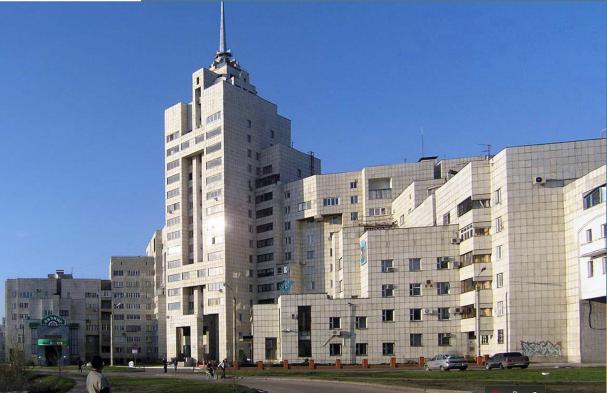
2. Residential complexes designed using block sections of complex configuration in Voronezh. In the 1980s, individual projects were largely constructed from brick. For the first time in Voronezh, T-shaped block sections of “beam structure” were included in the project of the embankment of the residential district № 27 of the left bank. The latitudinal sections commonly consisted of four apartments on each floor, as the strict requirements of the time for the insolation of apartments (at least three hours) did not allow them to be oriented to the north of the horizon. The residential houses of the embankment were composed of block sections of five and six apartments on the floor. The length of the sections was comparable to regular block sections of latitudinal orientation, which allowed for a higher density of construction. That was achieved due to the protrusions of the block sections in the southern direction where there were two two-bedroom apartments on the floor. Protrusions, consoles, the general step character of the composition of residential houses allowed a fascinating townplanning ensemble to be designed which was distinct from the curb of the right bank and the Chernavsky bridge of Voronezh. The apartment house located on the corner of the complex closer to the Chernavskaya dam looks particularly impressive. The highest part of the building, facing the geometric center of the city on the right bank, ends with a traditional spire. In
88
Issue № 2 (50), 2021 |
ISSN 2542-0526 |
this building, T-shaped sections of different storeys are interlocked making up a memorable, extraordinary image of a residential building. Architectural techniques in the construction of the complex are associated with both Russian constructivism of the early 20th century [13] and the stepped nature of the skyscrapers of the "Stalin’s Empire" [9, 18] (Fig. 2).
Fig. 2 Construction of the embankment in the district № 27 of the Left Bank of Voronezh. Author of the project: S.A. Gilev , Co-authors: A.K. Zabnin, S.M. Sorokin, V.V. Pankin (engineer). Photo: S. A. Gilev
A few extraordinary types of block sections of complex configuration are employed in the project "Town of Voronezh" of one of the distrits of the city’s North. The construction of residential buildings was performed in monolithic structures with a single step of transverse load-bearing walls (3.6 m). Exterior walls were largely made of three-layer reinforced concrete panels with quality finishes. T-shaped sections of different storeys and orientations in combination with ordinary block sections allowed one to design cozy, human-sized residential neighborhoods forming the entrance to the city from Moscow. As the number of apartments was clearly defined in the task and the building density was not supposed to be increased, T-shaped five-storey sections were planned with three apartments on a typical floor, which allowed for a building with houses of different orientations. Stepped block sections on the 8th
89