

ENC - ECDIS Symbols / SN_Circ243-Rev.2 - Guidelines For The Presentation Of Navigation-Related Symbols Terms And Abbreviations
.pdf
|
|
|
SN.1/Circ.243/Rev.2 |
|
|
|
|
Annex 1, page 9 |
|
|
|
|
|
|
|
Topic |
Symbol |
Description |
|
|
|
|
|
|
|
|
|
The graphical indication in the chart |
|
|
|
|
area of an alarm condition (A11.4.4 |
|
|
|
|
and 11.4.6, MSC.232 (82)) should |
|
|
|
|
be presented as a polygon or poly- |
|
|
Look-ahead |
|
line on the boundary of the area or |
|
|
|
point object causing the condition. |
||
|
alarm highlight |
|
||
|
|
The polygon or poly-line should be |
||
|
|
|
||
|
|
Example shows a depth area shallower |
drawn using a thick solid line style |
|
|
|
with recommended colour red. The |
||
|
|
than safety contour and a dangerous |
||
|
|
bounded area should have a |
||
|
|
wreck within the look-ahead safety |
||
|
|
transparent fill of the same colour. |
||
|
|
check area |
||
|
|
|
|
|
|
|
|
The graphical indication in the chart |
|
|
|
|
area of warning or caution |
|
|
|
|
conditions (see A11.4.4 and 11.4.6, |
|
|
|
|
MSC.232 (82)) should be presented |
|
|
|
|
as a polygon or poly-line on the |
|
|
Look-ahead |
|
boundary of the area or point object |
|
|
|
causing the condition. The polygon |
||
|
indication |
|
||
|
|
or poly-line should be drawn using a |
||
|
highlight |
|
||
|
|
thick solid line style with |
||
|
|
|
||
|
|
Example show point (wreck), restricted |
recommended colour yellow and |
|
|
|
area and line (fish stakes) |
adjacent thin lines of black on either |
|
|
|
|
side for visibility against a white |
|
|
|
|
(Day) background. The bounded |
|
|
|
|
area should not be filled. |
|
|
|
|
A danger bearing or clearing line |
|
|
|
|
should be presented as a single line |
|
|
|
|
with an arrowhead directed at the |
|
|
|
|
base of a charted object. The line |
|
|
|
|
should be drawn using a thin solid |
|
|
|
|
line style with the required colour |
|
|
Danger bearing |
|
red. A danger bearing should be |
|
|
The drawing is not to scale. The |
labelled with its bearing. The letters |
||
|
|
|||
|
|
example shows the default symbols for |
"NMT" should be used to indicate |
|
|
|
a light and a dangerous wreck at an |
"not more than". The letters "NLT" to |
|
|
|
unknown depth. |
indicate "not less than". |
|
|
|
|
Alphanumeric text used to label the |
|
|
|
|
danger bearing should be the same |
|
|
|
|
basic colour as the line. |
|
|
|
|
MSI point symbol should be |
|
|
|
|
presented as a box with the "MSI" |
|
|
|
|
inscribed inside it. The box should |
|
|
|
|
be centred at the position derived |
|
|
|
|
from the MSI message. The box |
|
|
MSI |
|
should be drawn using a thick solid |
|
|
|
line style. |
||
|
|
|
||
|
|
|
The MSI area symbol should be |
|
|
|
|
presented as a series of lines |
|
|
|
|
bounding a geographic area |
|
|
|
|
designated as "caution" to |
|
I:\CIRC\SN\01\SN.1-Circ.243-Rev.2.docx

SN.1/Circ.243/Rev.2
Annex 1, page 10
Topic |
Symbol |
Description |
|
|
|
|
|
navigation. Connecting lines should |
|
|
be drawn using thin dashed line |
|
|
style and using the same basic |
|
|
colour as the symbol itself. The area |
|
|
should be filled with a sparse |
|
|
pattern of MSI point symbols. |
|
|
Note that the source of MSI may be |
|
|
NAVTEX, AIS ASM function |
|
|
identifier 22 or 23 (SN.1/Circ.289), |
|
|
etc. |
|
|
|
|
|
Meteorological information symbols |
|
|
consist of two parts: |
|
|
• the weather station symbol; |
|
|
and |
|
|
• reference point and the wind |
|
|
shaft. |
|
|
The weather station symbol should |
|
|
be presented as a circle with "W" |
|
|
inscribed inside it. The circle should |
|
|
be centred at the position derived |
|
|
from the site location report binary |
|
|
message. The circle should not be |
|
|
more than 6 mm in diameter, drawn |
|
|
using a thin solid line style and |
|
|
using the same basic colour as AIS |
|
|
AtoN. The reference point symbol |
|
|
should be presented as a dot. The |
Meteorological |
|
dot should be more drawn using a |
information |
|
thin solid line style and using the |
|
|
same basic colour as AIS AtoN. |
|
|
Alphanumeric text may be used to |
|
|
label the weather station. |
|
|
The optional wind shaft should be |
|
|
used to represent wind force and |
|
|
direction as defined by WMO |
|
|
No.485, Appendix II-4, the surface |
|
|
plotting model. If wind force and |
|
|
direction is not available then there |
|
|
should be no environmental symbol. |
|
|
The wind shaft should be not more |
|
|
than 3 times the diameter of the |
|
|
weather station symbol. The length |
|
|
of barbs and pennants should not |
|
|
exceed the diameter of the weather |
|
|
station symbol. The wind shaft |
|
|
should be drawn using a thick solid |
|
|
line style and using the same basic |
I:\CIRC\SN\01\SN.1-Circ.243-Rev.2.docx

|
|
|
|
SN.1/Circ.243/Rev.2 |
|
|
|
|
|
Annex 1, page 11 |
|
|
|
|
|
|
|
|
Topic |
Symbol |
|
Description |
|
|
|
|
|
||
|
|
|
colour as AIS AtoN. The wind shaft |
||
|
|
|
is directed along the axis of the wind |
||
|
|
|
towards the centre of the station |
||
|
|
|
circle and stops at its |
||
|
|
|
circumference. Wind is represented |
||
|
|
|
by barbs and solid pennants. The |
||
|
|
|
full barbs representing 5 m s−1 or |
||
|
|
|
10 kn, the half barbs representing |
||
|
|
|
2.5 m s−1 or 5 kn and the solid |
||
|
|
|
pennant representing 25 m s−1 |
||
|
|
|
or 50 kn. All pennants and barbs lie |
||
|
|
|
to the left (clockwise) of the wind |
||
|
|
|
shaft in the northern hemisphere |
||
|
|
|
and to the right (counter clockwise) |
||
|
|
|
of the wind shaft in the southern |
||
|
|
|
hemisphere. Barbs are at an angle |
||
|
|
|
of 110° to 130° from the wind shaft. |
||
|
|
|
Pennants are triangles with their |
||
|
|
|
bases on the wind shaft. A calm |
||
|
|
|
should be indicated by a circle |
||
|
|
|
drawn around the weather station |
||
|
|
|
circle. Missing wind speed should |
||
|
|
|
be indicated by placing an "x" at the |
||
|
|
|
end of the wind shaft in lieu of the |
||
|
|
|
wind barbs. |
||
|
|
|
Note that the source of |
||
|
|
|
meteorological information may be |
||
|
|
|
AIS ASM function identifier 26 or 31 |
||
|
|
|
(SN.1/Circ.289), etc. |
||
|
|
|
|
||
|
|
|
Tidal and water level information |
||
|
|
|
symbol consist of three parts: |
||
|
|
|
• |
tidal symbol; |
|
|
|
|
• |
tidal flow symbol; |
|
|
|
|
• |
tidal gauge symbol. |
|
|
|
|
The tidal symbol should be |
||
|
|
|
presented as a diamond with "T" |
||
|
Tidal and water |
|
inscribed inside it. The diamond |
||
|
|
should be centred at the position |
|||
level information |
|
||||
|
derived from the site location report |
||||
|
|
|
|||
|
|
|
binary message. The diamond |
||
|
|
|
should be drawn using a thin solid |
||
|
|
|
line style and using the same basic |
||
|
|
|
colour as AIS AtoN. |
||
|
|
|
The optional tidal flow part of the |
||
|
|
|
symbol should be used to represent |
||
|
|
|
tidal speed and direction. If tidal |
||
|
|
|
speed and direction is not available |
||
I:\CIRC\SN\01\SN.1-Circ.243-Rev.2.docx
SN.1/Circ.243/Rev.2
Annex 1, page 12
Topic |
Symbol |
Description |
|
|
|
|
|
then there should be no tidal flow |
|
|
symbol. The tidal flow symbol |
|
|
should be drawn to the direction of |
|
|
the tidal current and using the same |
|
|
basic colour as AIS AtoN. |
|
|
The optional tidal gauge part of the |
|
|
symbol should be used to represent |
|
|
availability of water level |
|
|
information. If water level is not |
|
|
available then there should be no |
|
|
tidal gauge symbol. The tidal gauge |
|
|
symbol should be drawn using a |
|
|
thick solid line style, transparent fill |
|
|
and using the same basic colour as |
|
|
AIS AtoN. |
|
|
Note that the source of tidal |
|
|
information may be AIS ASM |
|
|
function identifier 31 |
|
|
(SN.1/Circ.289), etc. |
Topic |
Symbol |
Description |
|
|
|
|
|
Signal station should be presented |
|
|
as a diamond centred at the |
|
|
reported position of the signal |
|
|
station. The sides of the diamond |
|
|
should be the same basic colour as |
|
|
the AIS AtoN symbol. |
|
|
The symbol should be labelled with |
Signal station |
|
text "SS" centred in the diamond |
|
|
and the colour of the label should be |
|
|
the same colour as the symbol. |
|
|
Note that a signal station is a station |
|
|
capable of transmitting marine traffic |
|
|
signals. The source of signal station |
|
|
may be AIS ASM function identifier |
|
|
19 (SN.1/Circ.289), etc. |
|
|
|
|
|
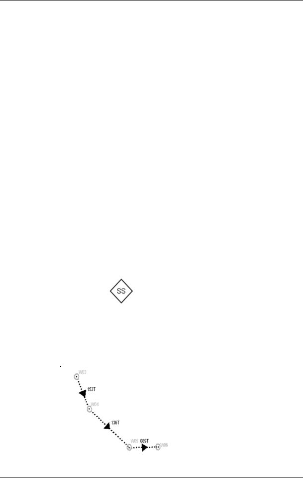
Route information is as a series of |
|
|
waypoints connected by one or |
|
|
more legs. Leg lines on the route |
|
|
information should be drawn using a |
Route |
|
thin dotted line style. They should |
information |
|
have a centred solid triangle with |
broadcast |
|
equal length of each side and |
|
|
should be the same basic colour as |
|
|
the AIS AtoN symbol. Solid triangle |
|
|
is centred on visible part of each |
|
|
leg. |
I:\CIRC\SN\01\SN.1-Circ.243-Rev.2.docx

SN.1/Circ.243/Rev.2
Annex 1, page 13
|
|
|
|
Leg lines on the route information |
|
|
|
|
|
may be labelled adjacent to their |
|
|
|
|
|
line with their course. The label |
|
|
|
|
|
should not interfere with text used to |
|
|
|
|
|
label the waypoint. Alphanumeric |
|
|
|
|
|
text used to label a leg line should |
|
|
|
|
|
be the same colour as the leg line. |
|
|
|
|
|
The colour of route type "mandatory |
|
|
|
|
|
route" should be different from other |
|
|
|
|
|
route types. |
|
|
|
|
|
Note that the source of route |
|
|
|
|
|
information may be AIS ASM |
|
|
|
|
|
function identifier 27 or 28 |
|
|
|
|
|
(SN.1/Circ.289), etc. |
|
|
|
|
|
|
|
|
Topic |
Symbol |
|
Description |
|
|
|
|
|
|
|
|
|
|
Berthing assignment should be |
|
|
|
|
|
presented as a box with the "BERTH" |
|
|
|
|
|
inscribed inside it. The box should be |
|
|
|
|
|
centred at the position derived from the |
|
|
|
|
|
berthing data message. The box should |
|
|
|
Berthing data |
|
be drawn using a thick solid line style |
|
|
|
|
and should be the same basic colour as |
|
||
|
|
|
|
||
|
|
|
the AIS AtoN symbol. |
|
|
|
|
|
Note that the source of berthing data |
|
|
|
|
|
may be AIS ASM function identifier 20 |
|
|
|
|
|
(SN.1/Circ.289), etc. |
|
|
|
|
|
Clearance time to enter port should be |
|
|
|
|
|
presented as a box with the "CTE" |
|
|
|
|
|
inscribed inside it. The box should be |
|
|
|
|
|
centred at the position derived from |
|
|
|
|
|
clearance time to enter port data |
|
|
|
Clearance time to |
|
message. The box should be drawn |
|
|
|
|
using a thick solid line style and should |
|
||
|
enter port |
|
|
||
|
|
be the same basic colour as the AIS |
|
||
|
|
|
|
||
|
|
|
AtoN symbol. |
|
|
|
|
|
Note that the source of clearance to |
|
|
|
|
|
enter port may be AIS ASM function |
|
|
|
|
|
identifier 18 (SN.1/Circ.289), etc. |
|
|
|
|
|
|
|
|
I:\CIRC\SN\01\SN.1-Circ.243-Rev.2.docx

SN.1/Circ.243/Rev.2 Annex 1, page 14
Area notice
Air gap
Area notice point symbol should be presented as a box with "AN" inscribed inside it. The box should be centred at the position derived from Area notice message. The box should be drawn using a thick solid line style and should be the same basic colour as the AIS AtoN symbol.
Area notice area symbol should be presented as a series of lines bounding a geographic area. Connecting lines should be drawn using the thin dashed line style and using the same basic colour as the symbol itself. The area should be filled with a sparse pattern of Area notice point symbols. Drawing priority of Area notice symbol is below Maritime Safety Information (MSI).
Note that the source of the area notice may be AIS ASM function identifier 22 or 23 (SN.1/Circ.289), etc.
Air gap symbols consist of two parts:
•the air gap symbol
•the air gap gauge symbol
The air gap symbol should be presented as a diamond with "A" inscribed inside it. The diamond should be centred at the position derived from the site location report binary message. The diamond should be drawn using a thin solid line style and using the same basic colour as AIS AtoN.
The air gap gauge part of the symbol should be used to represent availability of air gap information. If air gap is not available then there should be no air gap gauge symbol. The air gap gauge symbol should be drawn using a thick solid line style, transparent fill and using the same basic colour as AIS AtoN.
Note that the source of the air gap/air draught information may be AIS ASM function identifier 26 (SN.1/Circ.289), etc.
I:\CIRC\SN\01\SN.1-Circ.243-Rev.2.docx

SN.1/Circ.243/Rev.2
Annex 1, page 15
|
|
The environmental report symbol |
|
|
should be presented as a diamond with |
|
|
"ENV" inscribed inside it. The diamond |
|
|
should be centred at the position |
|
|
derived from the site location report |
|
|
binary message. The diamond should |
Environmental |
|
be drawn using a thin solid line style |
report |
|
and using the same basic colour as AIS |
|
|
AtoN. |
|
|
Note that the source of environmental |
|
|
information may be AIS ASM function |
|
|
identifier 26 or 31 (SN.1/Circ.289), etc. |
|
|
|
I:\CIRC\SN\01\SN.1-Circ.243-Rev.2.docx

SN.1/Circ.243/Rev.2
Annex 1, page 16
Table 5.1: Improved symbols for portrayal of AIS Aids to Navigation (AIS AtoN)
Type of AIS AtoN |
Symbol |
Symbol |
|
Description |
(Type of code in AIS msg. 21) |
(Physical) |
(Virtual) |
|
|
|
|
|
|
|
|
|
|
Solid diamond |
|
Portrayal when indication of type |
|
|
(Shown |
with chart symbol. Chart |
|
|
symbol not required for radar.) |
||
is not selected |
|
|
||
|
|
Note: Applicable only for Physical |
||
|
|
|
||
|
|
|
AIS AtoN |
|
Default, type not specified |
|
|
Physical: Solid diamond |
|
(0) |
|
|
(Shown with chart symbol. Chart |
|
Reference point (1) |
|
|
symbol not required for radar.) |
|
Light, without sectors (5) |
|
|
Virtual: Dotted diamond with cross |
|
Light, with sectors (6) |
|
|
hair centred at reported position |
|
Leading Light Front (7) |
|
|
|
|
Leading Light Rear (8) |
|
|
|
|
|
|
|
Solid diamond |
|
Fixed structure |
|
|
(Shown with chart symbol. Chart |
|
|
|
symbol not required for radar.) |
||
offshore/obstruction (3) |
|
|
||
|
|
Note: Fixed structure |
||
Light Vessel/LANBY/Rigs |
|
|
||
|
|
offshore/obstruction and Light |
||
(31) |
|
|
||
|
|
Vessel/LANBY/Rigs versions are |
||
|
|
|
||
|
|
|
not applicable for Virtual AIS AtoN |
|
|
|
|
Solid diamond with double circle of |
|
|
|
|
black inner circle on the top of |
|
Racon (2) |
|
|
diamond |
|
|
|
|
Note: |
Racon version is not |
|
|
|
applicable for Virtual AIS AtoN |
|
|
|
|
Physical: Solid diamond with cross |
|
|
|
|
on the top of diamond |
|
Emergency Wreck Mark |
|
|
(Shown with chart symbol. Chart |
|
|
|
symbol not required for radar.) |
||
(4) |
|
|
||
|
|
Virtual: Dotted diamond with cross |
||
|
|
|
||
|
|
|
hair centred at reported position and |
|
|
|
|
cross on the top of diamond |
|
|
|
|
Physical: Solid diamond with 2 |
|
|
|
|
triangles, one above the other, point |
|
|
|
|
upward, on top of diamond |
|
Beacon, Cardinal N (9) |
|
|
(Shown with chart symbol. Chart |
|
|
|
symbol not required for radar.) |
||
Floating, Cardinal Mark N |
|
|
||
|
|
Virtual: Dotted diamond with cross |
||
(20) |
|
|
||
|
|
hair centred at reported position and |
||
|
|
|
||
|
|
|
2 triangles, one above the other, |
|
|
|
|
points upward, on the top of |
|
|
|
|
diamond |
|
I:\CIRC\SN\01\SN.1-Circ.243-Rev.2.docx

|
|
|
|
SN.1/Circ.243/Rev.2 |
|
|
|
|
|
Annex 1, page 17 |
|
|
|
|
|
|
|
|
Type of AIS AtoN |
Symbol |
Symbol |
Description |
|
(Type of code in AIS msg. 21) |
(Physical) |
(Virtual) |
|
|
|
|
|
|
|
|
|
|
|
|
|
Physical: Solid diamond with 2 |
|
|
|
|
|
triangles, one above the other, base |
|
|
|
|
|
to base, on the top of diamond |
|
|
Beacon, Cardinal E (10) |
|
|
(Shown with chart symbol. Chart |
|
|
|
|
symbol not required for radar.) |
||
|
Floating, Cardinal Mark E |
|
|
||
|
|
|
Virtual: Dotted diamond with cross |
||
(21) |
|
|
|||
|
|
hair centred at reported position |
|||
|
|
|
|
||
|
|
|
|
and 2 triangles, one above the |
|
|
|
|
|
other, base to base, on the top of |
|
|
|
|
|
diamond |
|
|
|
|
|
Physical: Solid diamond with 2 |
|
|
|
|
|
triangles, one above the other, point |
|
|
|
|
|
downward, on the top of diamond |
|
|
Beacon, Cardinal S (11) |
|
|
(Shown with chart symbol. Chart |
|
|
|
|
symbol not required for radar.) |
||
|
Floating, Cardinal Mark S |
|
|
||
|
|
|
Virtual: Dotted diamond with cross |
||
(22) |
|
|
|||
|
|
hair centred at reported position |
|||
|
|
|
|
||
|
|
|
|
and 2 triangles, one above the |
|
|
|
|
|
other, points downward, on the top |
|
|
|
|
|
of diamond |
|
|
|
|
|
Physical: Solid diamond with 2 |
|
|
|
|
|
triangles, one above the other, point |
|
|
|
|
|
to point, on the top of diamond |
|
|
Beacon, Cardinal W (12) |
|
|
(Shown with chart symbol. Chart |
|
|
|
|
symbol not required for radar.) |
||
|
Floating, Cardinal Mark W |
|
|
||
|
|
|
Virtual: Dotted diamond with cross |
||
(23) |
|
|
|||
|
|
hair centred at reported position |
|||
|
|
|
|
||
|
|
|
|
and 2 triangles, one above the |
|
|
|
|
|
other, point to point, on the top of |
|
|
|
|
|
diamond |
|
|
|
|
|
Physical: Solid diamond with |
|
Beacon, Port hand (13) Beacon, |
|
|
rectangle, short side up, on the top |
||
|
|
of diamond (Shown with chart |
|||
|
Preferred |
|
|
||
|
|
|
symbol. Chart symbol not required |
||
|
Channel Port hand (15) Port |
|
|
||
|
|
|
for radar.) |
||
|
hand Mark (24) |
|
|
||
|
|
|
Virtual: Dotted diamond with cross |
||
Preferred Channel Port hand |
|
|
|||
|
|
hair centred at reported position and |
|||
(26) |
|
|
|||
|
|
rectangle, short side up, on the top |
|||
|
|
|
|
||
|
|
|
|
of diamond |
|
|
Beacon, Starboard hand |
|
|
Physical: Solid diamond with |
|
|
|
|
triangle, points upward, on the top |
||
(14) |
|
|
|||
|
|
of diamond (Shown with chart |
|||
|
Beacon, Preferred |
|
|
||
|
|
|
symbol. Chart symbol not required |
||
|
Channel Starboard hand |
|
|
||
|
|
|
for radar.) |
||
(16) |
|
|
|||
|
|
Virtual: Dotted diamond with cross |
|||
|
Starboard hand Mark (25) |
|
|
||
|
|
|
hair centred at reported position |
||
|
Preferred Channel |
|
|
||
|
|
|
and triangle, points upward, on the |
||
|
Starboard hand (27) |
|
|
||
|
|
|
top of diamond |
||
|
|
|
|
||
I:\CIRC\SN\01\SN.1-Circ.243-Rev.2.docx

SN.1/Circ.243/Rev.2
Annex 1, page 18
|
Type of AIS AtoN |
|
Symbol |
Symbol |
Description |
|||
(Type of code in AIS msg. 21) |
|
(Physical) |
(Virtual) |
|
|
|||
|
|
|
|
|
|
|
|
|
|
|
|
|
|
|
|
Physical: Solid diamond with 2 |
|
|
|
|
|
|
|
|
circles, one above the other, on the |
|
|
Beacon, Isolated danger |
|
|
|
|
top of diamond (Shown with chart |
||
|
|
|
|
|
symbol. Chart symbol not required |
|||
(17) |
|
|
|
|
|
|||
|
|
|
|
|
for radar.) |
|||
|
Isolated danger (28) Beacon, |
|
|
|
|
|||
|
|
|
|
|
Virtual: Dotted diamond with cross |
|||
|
Safe |
|
|
|
|
|||
|
|
|
|
|
hair centred at reported position |
|||
|
|
|
|
|
|
|
||
|
|
|
|
|
|
|
and 2 circles, one above the other, |
|
|
|
|
|
|
|
|
on the top of diamond |
|
|
|
|
|
|
|
|
Physical: Solid diamond with circle |
|
|
|
|
|
|
|
|
on the top of diamond |
|
|
Beacon, Safe water (18) Safe |
|
|
|
|
(Shown with chart symbol. Chart |
||
|
|
|
|
|
symbol not required for radar.) |
|||
|
Water (29) |
|
|
|
|
|||
|
|
|
|
|
Virtual: Dotted diamond with cross |
|||
|
|
|
|
|
|
|
||
|
|
|
|
|
|
|
hair centred at reported position |
|
|
|
|
|
|
|
|
and circle on the top of diamond |
|
|
|
|
|
|
|
|
Physical: Solid diamond with bold |
|
|
|
|
|
|
|
|
outlined "X" on the top of diamond |
|
|
|
|
|
|
|
|
(Shown with chart symbol. Chart |
|
|
Beacon, Special mark (19) |
|
|
|
|
symbol not required for radar.) |
||
|
|
|
|
|
Virtual: Dotted diamond with cross |
|||
|
Special Mark (30) |
|
|
|
|
|||
|
|
|
|
|
hair centred at reported position |
|||
|
|
|
|
|
|
|
||
|
|
|
|
|
|
|
and bold outlined "X" on the top of |
|
|
|
|
|
|
|
|
diamond |
|
|
Table 5.2: Portrayal of AIS AtoN indicating off position or failure |
|||||||
|
|
|
|
|
|
|
|
|
|
Type of failure condition |
|
Symbol |
|
|
Description |
|
|
|
|
(Physical) |
|
|
|
|
||
|
|
|
|
|
Failure is indicated using yellow caution colour for |
|
||
|
|
|
|
|
the basic diamond part of the symbol with cross |
|
||
|
AIS AtoN indicating to be |
|
|
|
hair centred at reported position and for text "Off |
|
||
|
|
|
|
Posn" in top of the Physical AIS AtoN. |
|
|||
|
in |
|
|
|
|
|||
|
|
|
|
|
|
|
|
|
|
Off Position |
|
|
|
Note: Physical AIS AtoN indicates realtime EPFS |
|
||
|
|
|
|
|
|
|||
|
|
|
|
|
position of drifting AtoN (obstacle). |
|
||
|
|
|
|
|
|
|
||
|
|
|
|
|
Failure is indicated using yellow caution colour with |
|
||
|
AIS AtoN indicating Lights |
|
|
|
text "Unlit" in top of the Physical AIS AtoN. |
|
||
|
|
|
|
|
|
|
|
|
|
failure |
|
|
|
|
|
|
|
|
|
|
|
|
|
|
||
|
|
|
|
|
Failure is indicated using yellow caution colour with |
|
||
|
AIS AtoN indicating Racon |
|
|
|
text "Racon err" in top of the Physical AIS AtoN. |
|
||
|
|
|
|
|
|
|
|
|
|
failure |
|
|
|
|
|
|
|
|
|
|
|
|
|
|
|
|
I:\CIRC\SN\01\SN.1-Circ.243-Rev.2.docx